YIO modules for YSSC2P/YSSC3P/YMDS2P cards
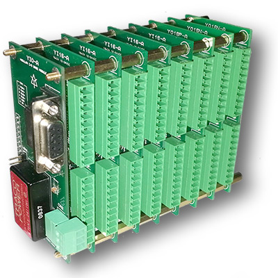
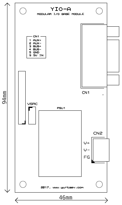
Provides the 8P8C bus connector and isolated DC power supply for all connected modules
| YIO-B - YIO (RJ-45) | ||
|---|---|---|
| 1 | AUX+ | Auxiliry bus non-inverting line |
| 2 | AUX- | Auxiliry bus inverting line |
| 3 | BUS+ | Main bus non-inverting line |
| 4 | GND | |
| 5 | GND | |
| 6 | BUS- | Main bus inverting line |
| 7 | ||
| 8 | ||
| YIO-A - CN1 (DSub-9F) | ||
|---|---|---|
| 1 | AUX+ | Auxiliry bus non-inverting line |
| 2 | AUX- | Auxiliry bus inverting line |
| 3 | BUS+ | Main bus non-inverting line |
| 4 | BUS- | Main bus inverting line |
| 5 | GND | |
| 6 | ||
| 7 | ||
| 8 | ||
| 9 | 5VDC | Power input (or output if DC/DC module is installed) |
J3: Phoenix Contact MC 1,5/3-ST-3,5 or equivalent
| J3 / CN2 | ||
|---|---|---|
| 1 | FG | Fame ground |
| 2 | V- | Ext power supply negative |
| 3 | V+ | Ext power supply positive 18-36VDC input |
| J2 / VSRC | ||
|---|---|---|
| 1-2 | 5V | Use 5VDC supplied thru DB9 connector |
| 2-3 | 24V | Use on-board DC-DC converter |
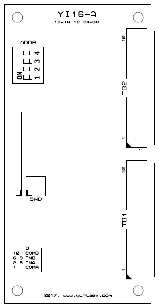
Address DIP switches on slave boards
| ADDR | ||
|---|---|---|
| 1 | A0 | Address + 1 |
| 2 | A1 | Address + 2 |
| 3 | A2 | Address + 4 |
| 4 | A3 | Address + 8 |
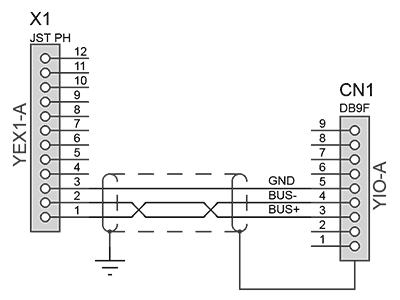
YIO-B connects to YEX3 with a straight thru shielded or unshielded ethernet cable with T568A/T568B pinout
YIO-A Connection
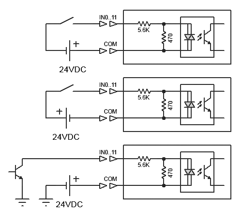
The module provides 16 x 24VDC optoisolated inputs. Inputs are arranged in 4 groups. Each group can be wired for either sinking or sourcing.
TB1, TB2: Phoenix Contact MC 1,5/10-ST-3,5 or equivalent
| TB2 | ||
|---|---|---|
| 10 | COMB | Common B for inputs 12..15 |
| 9 | IN15 | Inputs B 12..15 |
| 8 | IN14 | |
| 7 | IN13 | |
| 6 | IN12 | |
| 5 | IN11 | Inputs A 8..11 |
| 4 | IN10 | |
| 3 | IN9 | |
| 2 | IN8 | |
| 1 | COMA | Common A for inputs 8..11 |
| TB1 | ||
|---|---|---|
| 10 | COMB | Common B for inputs 4..7 |
| 9 | IN7 | Inputs B 4..7 |
| 8 | IN6 | |
| 7 | IN5 | |
| 6 | IN4 | |
| 5 | IN3 | Inputs A 0..3 |
| 4 | IN2 | |
| 3 | IN1 | |
| 2 | IN0 | |
| 1 | COMB | Common A for inputs 0..3 |
Example connection:
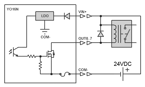
The module provides 16 optoisolated MOSFET sinking (common positive) outputs. Each TB is either protected with a 0.5A fuse or using current-protected MOSFETs.
TB1, TB2: Phoenix Contact MC 1,5/10-ST-3,5 or equivalent
| TB2 | ||
|---|---|---|
| 10 | COM- | Field power input: negative |
| 9 | OUT15 | Outputs 8..15 (sinking) |
| 8 | OUT14 | |
| 7 | OUT13 | |
| 6 | OUT12 | |
| 5 | OUT11 | |
| 4 | OUT10 | |
| 3 | OUT9 | |
| 2 | OUT8 | |
| 1 | VIN+ | Field power input: positive |
| TB1 | ||
|---|---|---|
| 10 | COM- | Field power input: negative |
| 9 | OUT7 | Outputs 0..7 (sinking) |
| 8 | OUT6 | |
| 7 | OUT5 | |
| 6 | OUT4 | |
| 5 | OUT3 | |
| 4 | OUT2 | |
| 3 | OUT1 | |
| 2 | OUT0 | |
| 1 | VIN+ | Field power input: positive |
Example connection:
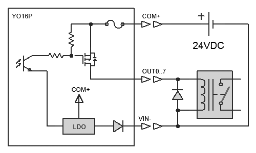
The module provides 16 optoisolated MOSFET sourcing (common ground) outputs. Each TB is either protected with a 0.5A fuse.
TB1, TB2: Phoenix Contact MC 1,5/10-ST-3,5 or equivalent
| TB2 | ||
|---|---|---|
| 10 | VIN- | Field power input: negative |
| 9 | OUT15 | Outputs 8..15 (sourcing) |
| 8 | OUT14 | |
| 7 | OUT13 | |
| 6 | OUT12 | |
| 5 | OUT11 | |
| 4 | OUT10 | |
| 3 | OUT9 | |
| 2 | OUT8 | |
| 1 | COM+ | Field power input: positive |
| TB1 | ||
|---|---|---|
| 10 | VIN- | Field power input: negative |
| 9 | OUT7 | Outputs 0..7 (sourcing) |
| 8 | OUT6 | |
| 7 | OUT5 | |
| 6 | OUT4 | |
| 5 | OUT3 | |
| 4 | OUT2 | |
| 3 | OUT1 | |
| 2 | OUT0 | |
| 1 | COM+ | Field power input: positive |
Example connection:
The module provides 2 channels, each:
J2, J3: 3M 10120-3000PE 20 pin MDR or equivalent connectors
| J2/J3 | |||
|---|---|---|---|
| 1 | AGND | 11 | AGND |
| 2 | AOUT | 12 | |
| 3 | 13 | ||
| 4 | OUT drain (to load) | 14 | OUT source (PSU negative) |
| 5 | GND | 15 | GND |
| 6 | A | 16 | A/ |
| 7 | B | 17 | B/ |
| 8 | Z | 18 | Z/ |
| 9 | IN | 19 | IN |
| 10 | 20 | +5VDC out * | |
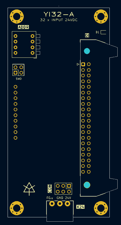
The module provides 32 x 24VDC optoisolated inputs, sinking/sourcing jumper selectable. Threshold voltage is ~19V, current at 24VDC is ~2mA
DI: .1" pitch double row IDC 40 connector
| DI | |||
|---|---|---|---|
| 1 | 2 | ||
| 3 | 4 | ||
| 5 | COM | 6 | COM |
| 7 | 8 | ||
| 9 | IN1F | 10 | IN0F |
| 11 | IN1E | 12 | IN0E |
| 13 | IN1D | 14 | IN0D |
| 15 | IN1C | 16 | IN0C |
| 17 | IN1B | 18 | IN0B |
| 19 | IN1A | 20 | IN0A |
| 21 | IN19 | 22 | IN09 |
| 23 | IN18 | 24 | IN08 |
| 25 | IN17 | 26 | IN07 |
| 27 | IN16 | 28 | IN06 |
| 29 | IN15 | 30 | IN05 |
| 31 | IN14 | 32 | IN04 |
| 33 | IN13 | 34 | IN03 |
| 35 | IN12 | 36 | IN02 |
| 37 | IN11 | 38 | IN01 |
| 39 | IN10 | 40 | IN00 |
X24: Phoenix Contact MC 1,5/3-ST-3,5 or equivalent
| X24 | |
|---|---|
| 1 | Frame ground |
| 2 | GND |
| 3 | +24V |
| COM | |||||
|---|---|---|---|---|---|
| 2 | GND | 4 | COM | 6 | +24V |
| 1 | GND | 3 | COM | 5 | +24V |
Jumpers 1-3 and 2-4 - sinking inputs, connect to +24V sourcing outputs
Jumpers 3-5 and 4-6 - sourcing inputs, connect to sinking (open collector) outputs
| D1 LED | |
|---|---|
| Blinking | Host communicaion |
| Pink | Initialization |
| Green | Normal operation |
| Yellow | Host connection |
Example connection:
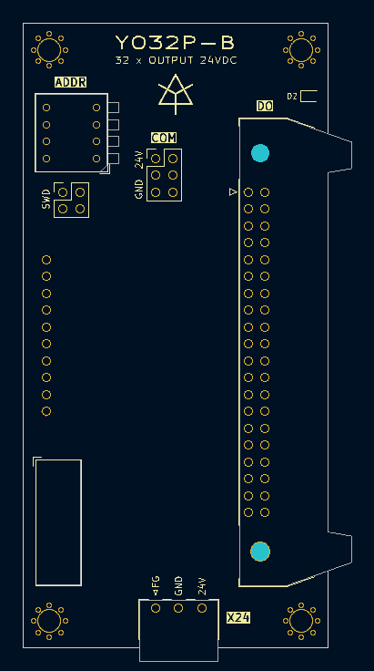
The module provides 32 x 24VDC isolated outputs sourcing up to 150mA each. Overcurrent protected. The module also provides to the NC voltages and currents at each output, field power voltage and driver chips temperatures. With software controlled weak pull-ups on outputs broken connections can be diagnosed.
DO: .1" pitch double row IDC 40 connector
| DO | |||
|---|---|---|---|
| 1 | GND | 2 | +24V |
| 3 | GND | 4 | +24V |
| 5 | COM | 6 | COM |
| 7 | 8 | ||
| 9 | OUT1F | 10 | OUT0F |
| 11 | OUT1E | 12 | OUT0E |
| 13 | OUT1D | 14 | OUT0D |
| 15 | OUT1C | 16 | OUT0C |
| 17 | OUT1B | 18 | OUT0B |
| 19 | OUT1A | 20 | OUT0A |
| 21 | OUT19 | 22 | OUT09 |
| 23 | OUT18 | 24 | OUT08 |
| 25 | OUT17 | 26 | OUT07 |
| 27 | OUT16 | 28 | OUT06 |
| 29 | OUT15 | 30 | OUT05 |
| 31 | OUT14 | 32 | OUT04 |
| 33 | OUT13 | 34 | OUT03 |
| 35 | OUT12 | 36 | OUT02 |
| 37 | OUT11 | 38 | OUT01 |
| 39 | OUT10 | 40 | OUT00 |
X24: Phoenix Contact MC 1,5/3-ST-3,5 or equivalent
| X24 | |
|---|---|
| 1 | Frame ground |
| 2 | GND |
| 3 | +24V |
| COM | |||||
|---|---|---|---|---|---|
| 2 | GND | 4 | COM | 6 | +24V |
| 1 | GND | 3 | COM | 5 | +24V |
Jumpers 1-3 and 2-4 - pins DO.5 DO.6 (COM) connectedd to GND
Jumpers 3-5 and 4-6 - pins DO.5 DO.6 (COM) connectedd to +24V
| D1 LED | |
|---|---|
| Blinking | Host communicaion |
| Pink | Initialization |
| Blue | 24V field power undervoltage |
| Green | Normal operation |
| Yellow | Host connection |
| Red | Overcurrent/overtemperature |
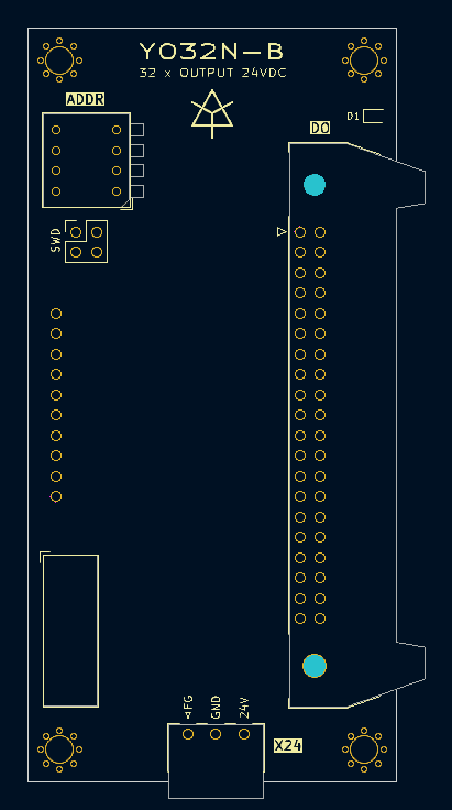
The module provides 32 x 24VDC isolated outputs sinking up to 600mA each. Overcurrent and overtemperature protected with fault reporting. Switcheable 0.1mA diagnostic current for open load detection.
DO: .1" pitch double row IDC 40 connector
| DO | |||
|---|---|---|---|
| 1 | GND | 2 | +24V |
| 3 | GND | 4 | +24V |
| 5 | 6 | ||
| 7 | 8 | ||
| 9 | OUT1F | 10 | OUT0F |
| 11 | OUT1E | 12 | OUT0E |
| 13 | OUT1D | 14 | OUT0D |
| 15 | OUT1C | 16 | OUT0C |
| 17 | OUT1B | 18 | OUT0B |
| 19 | OUT1A | 20 | OUT0A |
| 21 | OUT19 | 22 | OUT09 |
| 23 | OUT18 | 24 | OUT08 |
| 25 | OUT17 | 26 | OUT07 |
| 27 | OUT16 | 28 | OUT06 |
| 29 | OUT15 | 30 | OUT05 |
| 31 | OUT14 | 32 | OUT04 |
| 33 | OUT13 | 34 | OUT03 |
| 35 | OUT12 | 36 | OUT02 |
| 37 | OUT11 | 38 | OUT01 |
| 39 | OUT10 | 40 | OUT00 |
X24: Phoenix Contact MC 1,5/3-ST-3,5 or equivalent
| X24 | |
|---|---|
| 1 | Frame ground |
| 2 | GND |
| 3 | +24V |
| D1 LED | |
|---|---|
| Blinking | Host communicaion |
| Pink | Initialization |
| Green | Normal operation |
| Yellow | Host connection |
| Red | Overcurrent/overtemperature |
The adapter board with 2 IDC40 connectors for YI32 uplink and MR-50M + MR-20M with QX535/QX539 compatible pinout
The adapter board with 2 IDC40 connectors for YO32 uplink and MR-50F + MR-20F with QX539 compatible pinout
The adapter board with 3 IDC40 connectors for YO32 uplink and 2xMR-50F with QX535 compatible pinout
RS-485, half-duplex, 5Mbps, 8-N-1, LSB first.
Controller request:
| byte 0 | 1 | 2 .. N+1 | N+2 |
|---|---|---|---|
| 0x80 | addr | code | arg1 .. argN | CRC-8 |
Slave reply:
| byte 0 | 1 | 2 .. M+1 | M+2 |
|---|---|---|---|
| addr | code | dataM .. dataM | CRC-8 |
Slave address is 0..15. The polynomial used for CRC-8 is 0x8c: x8 + x5 + x4 + 1. A slave must start reply transmission within 10us after receiving a request.
Request:
| byte 0 | 1 | 2 |
|---|---|---|
| 0x80 | addr | 1 | CRC-8 |
Reply:
| byte 0 | 1 | 2 | 3 |
|---|---|---|---|
| addr | 1 | 1=YI16 2=YO16N/P 5=YAO2 0x11=YI32 0x12=YO32P 0x13=YO32N | CRC-8 |
Request:
| byte 0 | 1 | 2 |
|---|---|---|
| 0x80 | addr | 2 | CRC-8 |
Reply:
| byte 0 | 1 | 2 | 3 | 4 |
|---|---|---|---|---|
| addr | 2 | outputs 7..0 | outputs 15..8 | CRC-8 |
Request:
| byte 0 | 1 | 2 | 3 | 4 |
|---|---|---|---|---|
| 0x80 | addr | 3 | outputs 7..0 | outputs 15..8 | CRC-8 |
Reply:
| byte 0 | 1 | 2 |
|---|---|---|
| addr | 3 | CRC-8 |
Request:
| byte 0 | 1 | 2 |
|---|---|---|
| 0x80 | addr | 4 | CRC-8 |
Reply:
| byte 0 | 1 | 2 | 3 | 4 |
|---|---|---|---|---|
| addr | 4 | inputs 7..0 | inputs 15..8 | CRC-8 |
Request:
| byte 0 | 1 | 2 | 3 | 4 | 5 | 6 | 7 |
|---|---|---|---|---|---|---|---|
| 0x80 | addr | 5 | 0 idx1 0 idx0 0 out1 0 out0 | aout 0 low | aout 0 hi | aout 1 low | aout 1 hi | CRC-8 |
Reply:
| byte 0 | 1 | 2 | 3 | 4 | 5 | 6 | 7 |
|---|---|---|---|---|---|---|---|
| addr | 5 | 0 idx1 0 idx0 0 in1 0 in0 | enc 0 low | enc 0 hi | enc 1 low | enc 1 hi | CRC-8 |
Request:
| byte 0 | 1 | 2 | 3 | 4 | 5 | 6 | 7 |
|---|---|---|---|---|---|---|---|
| 0x80 | addr | 0x12 | outputs 7..0 | outputs 15..8 | outputs 23..16 | outputs 31..24 | 0x01=enable diagnostic current | CRC-8 |
Reply:
| byte 0 | 1 | 2 | 3 | 4 | 5 | 6 | 7 |
|---|---|---|---|---|---|---|---|
| addr | 0x12 | 0x80=overcurrent, 0-open load, 1-overcurrent | outputs 7..0 | outputs 15..8 | outputs 23..16 | outputs 31..24 | CRC-8 |
Request:
| byte 0 | 1 | 2 | 3 | 4 | 5 | 6 | 7 |
|---|---|---|---|---|---|---|---|
| 0x80 | addr | 0x13 | outputs 7..0 | outputs 15..8 | outputs 23..16 | outputs 31..24 | 0x01=enable pull-downs | CRC-8 |
Reply:
| byte 0 | 1 | 2 | 3 | 4 | 5 | 6 | 7 |
|---|---|---|---|---|---|---|---|
| addr | 0x13 | 0x80=overcurrent, 0x40=undervoltage, 0..7 data type | data0_lo | data0_hi | data1_lo | data1_hi | CRC-8 |
Request:
| byte 0 | 1 | 2 |
|---|---|---|
| 0x80 | addr | 0x14 | CRC-8 |
Reply:
| byte 0 | 1 | 2 | 3 | 4 | 5 | 6 |
|---|---|---|---|---|---|---|
| addr | 0x14 | inputs 7..0 | inputs 15..8 | inputs 23..16 | inputs 31..24 | CRC-8 |
Request:
| byte 0 |
|---|
| 0xED |
Reply: none